Torsion
Torsion refers to the twisting of a specimen when it is loaded by couples (or moments) that produce rotation about the longitudinal axis. Applications include aircraft engines, car transmissions, and bicycles, etc.Units
Force X distance [lb-in or N-m]Notation and Convention
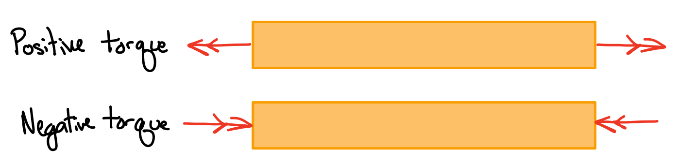
Sign convention
- \( \phi > 0 \) : counter clockwise
- \( \phi < 0 \) : clockwise
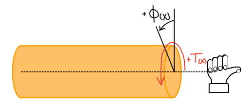
Right hand rule
Equilibrium
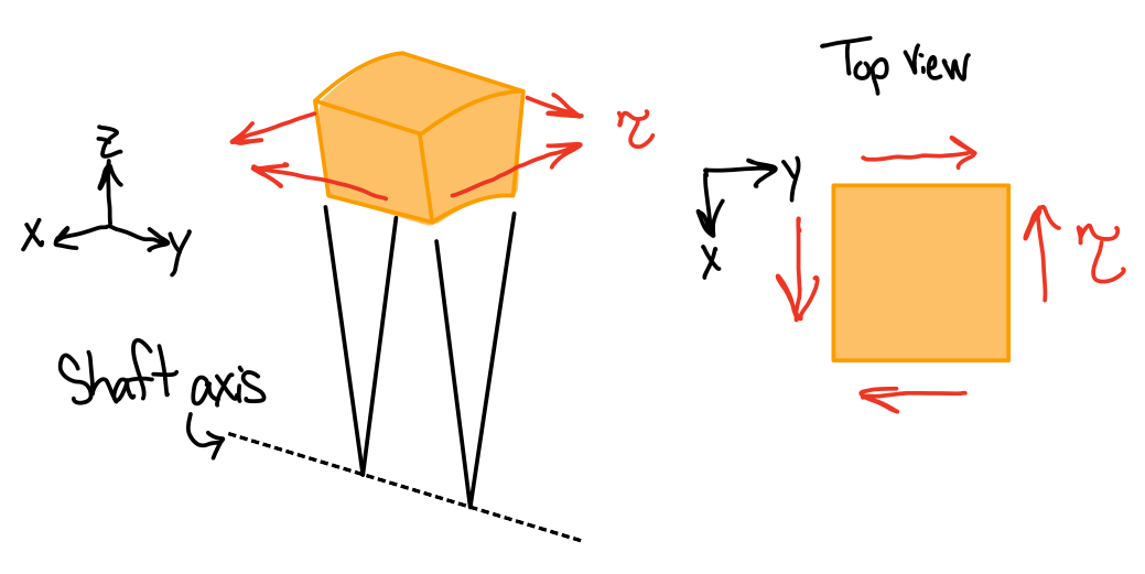
Single element shear stresses
- Statically indeterminate: must consider shaft deformations.
- Multi-planar: equilibrium requires the existence of shear stresses on the faces formed by the two planes containing the axis of the shaft
Assumptions

Torsion lines
- For circular shafts (hollow and solid): cross-sections remain plane and undistorted due to axisymmetric geometry
- For non-circular shafts: cross-sections are distorted when subject to torsion
- Linear and elastic deformation
Shear Strain: Geometry of Deformation
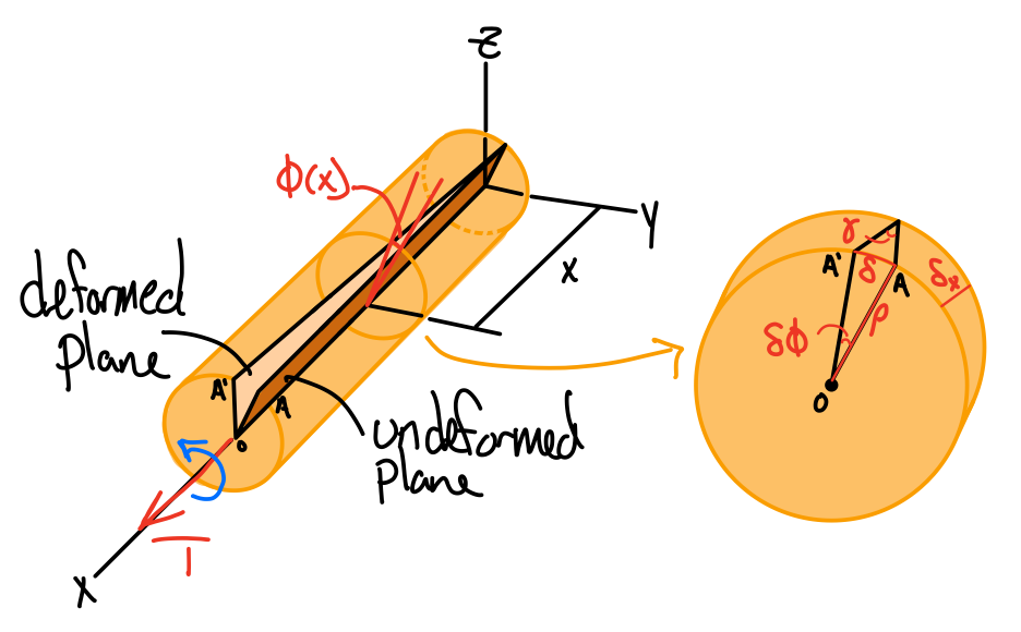
Deformation
The twist rate is given by.
Moving terms.
Arc length.
- is proportional to the angle of twist
- varies linearly with the distance from the axis of the shaft
- is maximum at the surface
Shear Stress: Torsion Formula
Geometry
Hooke's law.
From equilibrium.
Elastic torsion formula.
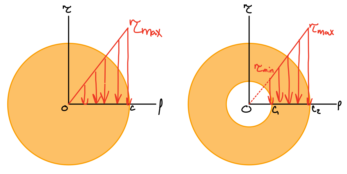
Stress distribution
Power.
Shear Stress: Polar Moment of Inertia
Solid shaft (radius and diameter). #tor-pmi
Hollow shaft (inner and outer radius). #tor-hol
Heads up!
For a moment of inertia summary, go to the "Moment of Inertia Summary" section of the Bending page.
Shear Stress: Angle of Twist
From observation:- The angle of twist of the shaft is proportional to the applied torque
- The angle of twist of the shaft is proportional to the length
- The angle of twist of the shaft decreases when the diameter of the shaft increases
Angle of twist.
Torsional stiffness.
Torsional flexibility.
Types of Material Failure
Ductile materials generally fail in shear
Heads up - Extra!
Torsion of thin-walled hallow shafts builds on this content.
In general, the maximum shear stress is given by
Gear Systems
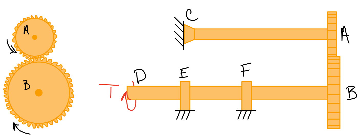
Gear system
Common assuptions:
- Gears are perfectly rigid.
- The rotation axis is perfectly fixed in space.
- Gear teeth are evenly spaced and perfectly shaped so there is no gap to create lost motion.
- Gear tooth faces are perfectly smooth so there is no slip.
- Mated gears twist through the same arc length.
To solve:
- Draw a FBD for each shaft.
- Use the torsion equilibrium equations of each shaft to find the recation forces and torques.
- Use the shear stress equation to find the stresses in the shaft.
Gear ratio.
Angle of twist
Extra!
Power transmition can be used to find shear stress in gear shafts.
Maximum shear stress: