Free body diagrams
A free-body diagram (abbreviated as FBD, also called force diagram) is a diagram used to show the magnitude and direction of all applied forces, moments, and reaction and constraint forces acting on a body. They are important and necessary in solving complex problems in mechanics.
What is and is not included in a free-body diagram is important. Every free-body diagram should have the following:
- The body represented as a dot if it is a point mass, and the body itself if it is a rigid body.
- The external forces/moments. The force vector should indicate: relative magnitude, point of application, and the direction.
- A properly defined coordinate system
A free-body diagram should not include the following:
- Bodies other than the body we are interested in.
- Forces applied by the body
- Internal forces depending on the chosen system. For example, a free-body diagram on a truss should not include the forces between individual truss members.
- Kinematic quantities (velocity and acceleration).
Warning: Always assume the direction of forces/moments to be positive according to the appropriate coordinate system. #warning1
Warning: If forces/moments are present, always begin with a free-body diagram. #warning2
Vector representation in FBDs
Many problems involve setting up a free body diagram with assumed directions for unknown forces or moments.
Heads up!
Truss assumptions builds on this content later in the course.
Pulley idealizations
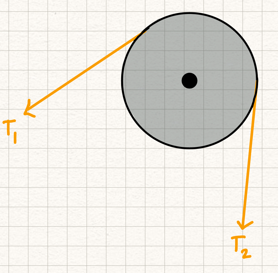
In this course we assume that a pulley is frictionless, meaning that the magnitude of the tensile force of the rope on either side of a pulley will be the same. Pulley Assumptions
Spring idealizations
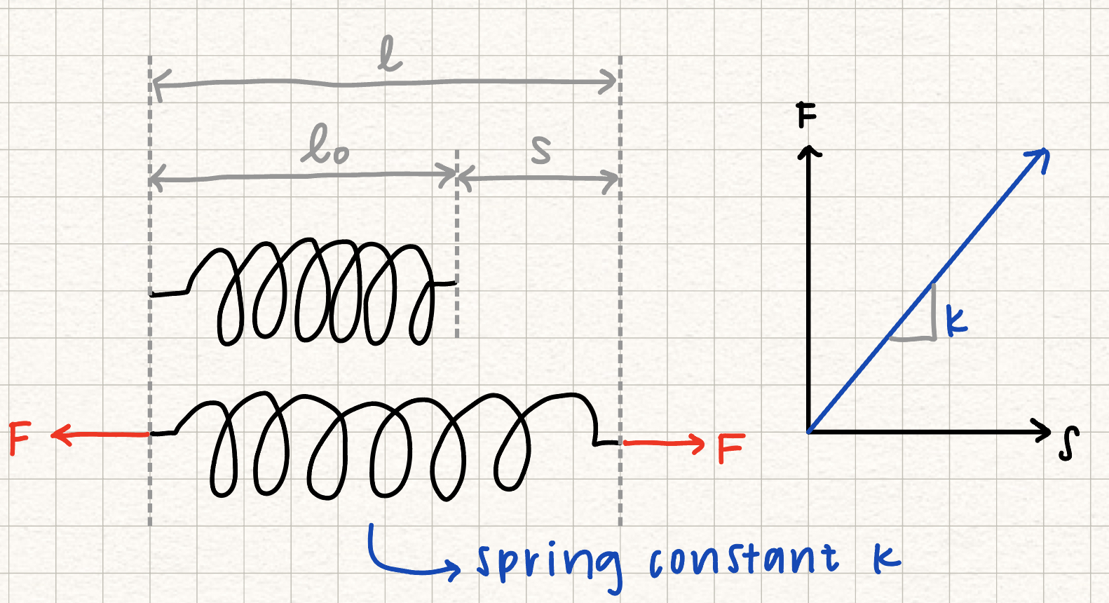
In this course, we assume springs are linearly elastic, which means that the force (tension) in the spring is linearly proportional to the extension of the spring (\( s \)) through the spring constant, \( k \). Spring force-extension relation
Spring extension
Smooth surface idealizations
If a surface is described as "smooth", we assume that there is no frictional force on the surface. Therefore, any force applied by the surface is normal to the surface.