Pure Bending
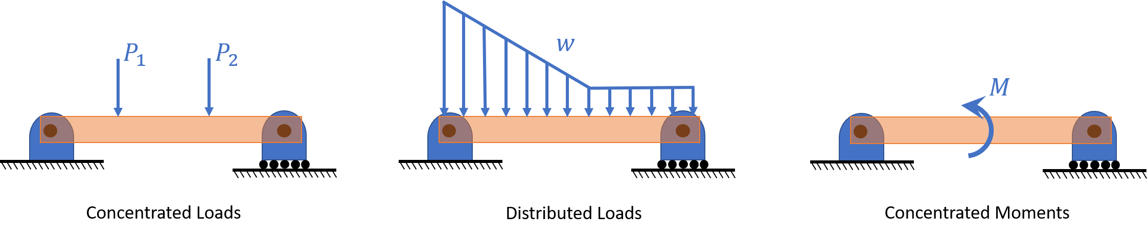
Transverse loads applied to a beam causes deflections, primarily up or down is referred to as bending. Bending stresses depend on the beams cross-section, length, and material properties.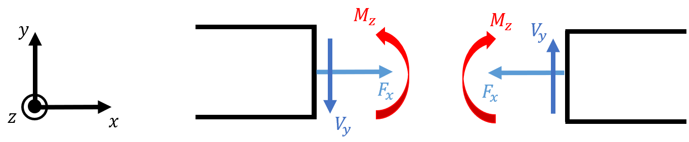
Pure Bending
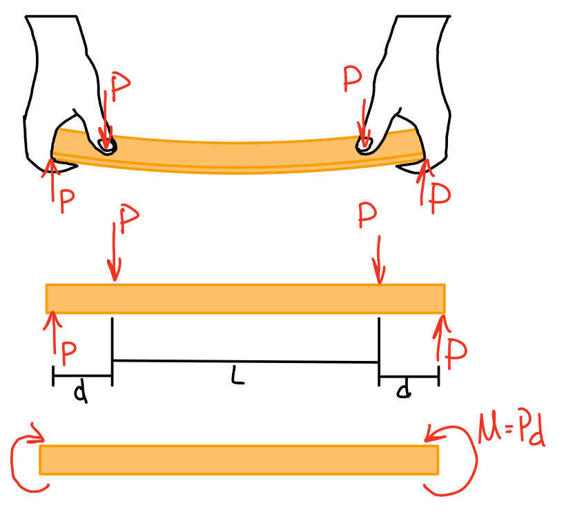
Geometry of Deformation
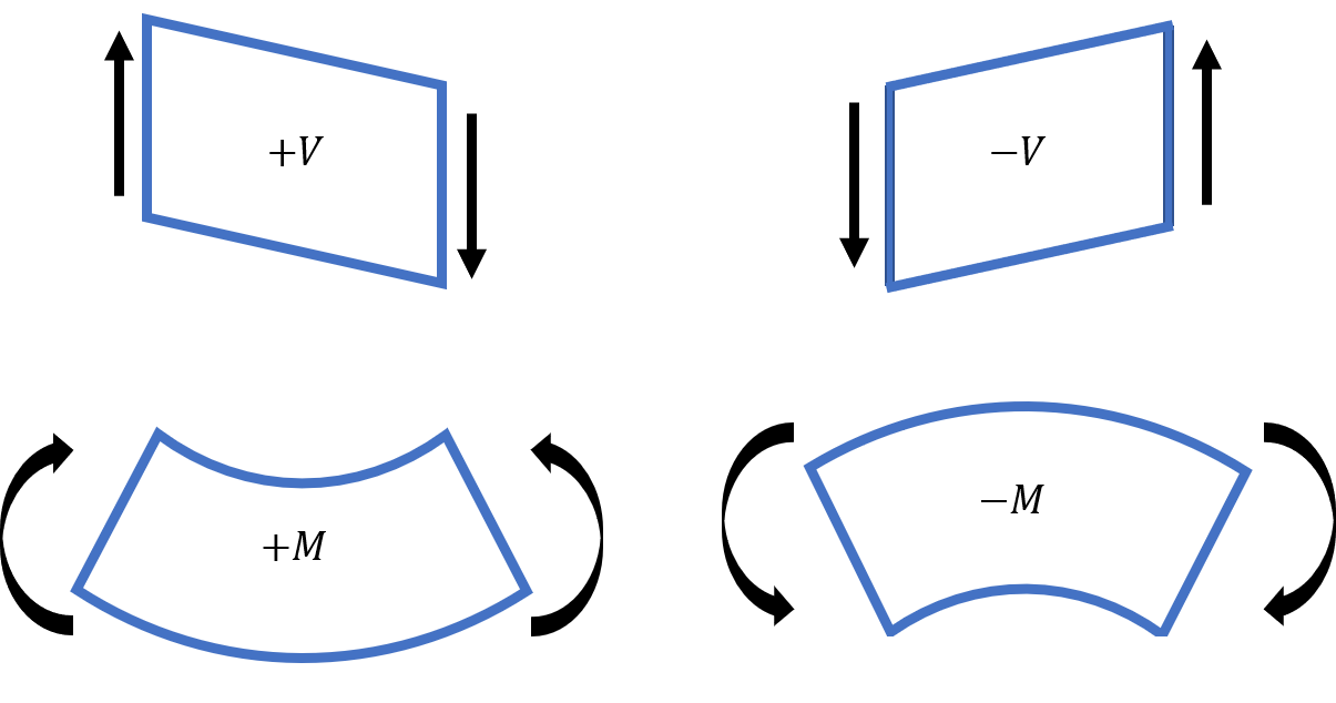
Bending diagram
-
Plane sections remain plane \( \rightarrow \)no shear stress/strains.
Therefore:Also, traction free boundary conditions yields...
-
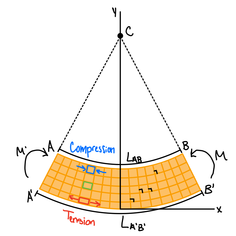
There is a Neutral axis between the top and the bottom where the length does not change.
-
The beam deforms into a circular arc where the top surface (\( AB \)) is in compression , and the bottom surface (\( AB ^\prime \)) is in tension.
- Any point in the beam is in a state of uniaxial normal stress.
- Finding stresses is a statically indeterminate problem.
Stress-Strain Variations
Material Behavior: linear elastic beams
Elastic range: bending moment is such that the normal stresses remain below the yield strength. Hooke’s law combined with equilibrium.
Moment-curvature equation. #mmt-crv
First Moment of Area: Centroid of an Area
The first moment of the area A with respect to the z-axis is given by \( Q_x = \int_A y dA = \Sigma yA \) . The first moment of the area A with respect to the y-axis is given by \( Q_y = \int_A x dA = \Sigma zA \). \( (\overline{x}, \overline{y}) \)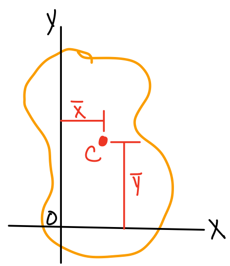
Centroid of a body
x coordinate.
y coordinate.
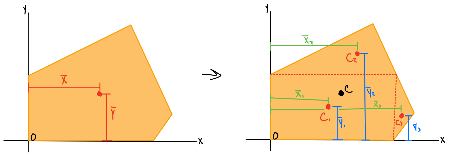
Centroid of a composite body
Composite x coordinate
Composite y coordinate
Second Moment or Area Moment of Inertia
The moment of inertia of the area \( A \) with respect to the x-axis. x-axis second moment.
y-axis second moment.
Note: polar moment of inertia in this plane
Polar moment of Inertia.
Parallel axis theorem.
Summary: Moment of Inertia
| Shape | Diagram | Equations |
|---|---|---|
| Rectangle | 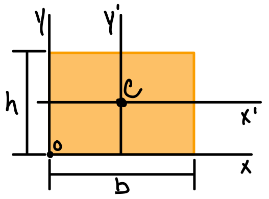 | \( \bar{I_{x'}} = \frac{1}{12}b h^3 \) \( \bar{I_{y'}} = \frac{1}{12}b^3 h \) \( I_x = \frac{1}{3}b h^3 \) \( I_y = \frac{1}{3}b^3 h \) \( J_c = \frac{1}{12}bh(b^2+h^2) \) |
| Triangle | 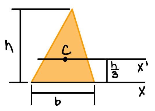 | \( \bar{I_{x'}} = \frac{1}{36}bh^3 \) \( I_x = \frac{1}{12}bh^3 \) |
| Circle | 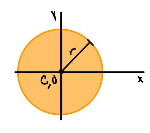 | \( \bar{I_x} = \bar{I_y} = \frac{1}{4} \pi r^4 \) \( J_O= \frac{1}{2} \pi r^4 \) |
| Semicircle | 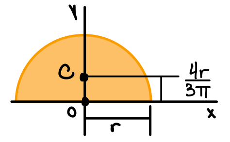 | \( I_x = I_y = \frac{1}{8} \pi r^4 \) \( J_O = \frac{1}{4} \pi r^4 \) |
| Quarter circle | 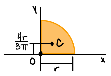 | \( I_x = I_y = \frac{1}{16} \pi r^4 \) \( J_O = \frac{1}{8} \pi r^4 \) |
| Ellipse | 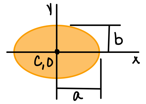 | \( \bar{I_x} = \frac{1}{4} \pi a b^3 \) \( \bar{I_y} = \frac{1}{4} \pi a^3 b \) \( J_O = \frac{1}{4} \pi ab(a^2+b^2) \) |
| Mass moment of inertia | Area moment of inertia | |||
|---|---|---|---|---|
| Other names | First moment of area | Second moment of area | Polar moment of area | |
| Description | Determines the torque needed to produce a desired angular rotation about an axis of rotation (resistance to rotation) | Determines the centroid of an area | Determines the moment needed to produce a desired curvature about an axis(resistance to bending) | Determines the torque needed to produce a desired twist a shaft or beam(resistance to torsion) |
| Equations | ||||
| Units | \( mass*length^2 \) | \( length^3 \) | \( length^4 \) | \( length^4 \) |
| Typical Equations | ||||
| Courses | TAM 212 | TAM 251 | TAM 210, TAM 251 | TAM 251 |
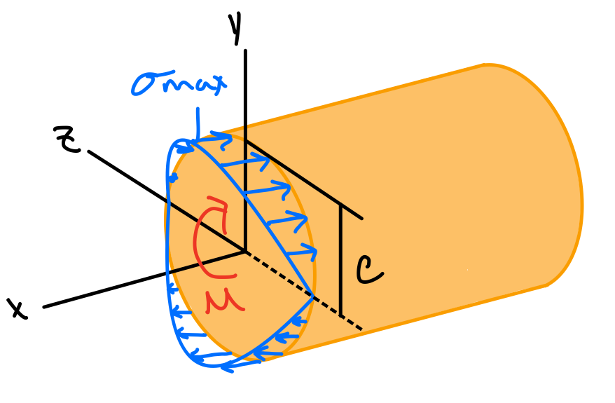
Maximum Normal Stress
From equilibrium: the centroid is located at \( \bar{y}=0 \), i.e., the neutral axis passes through the centroid of the section. Elastic flextural formula. #ela-flx
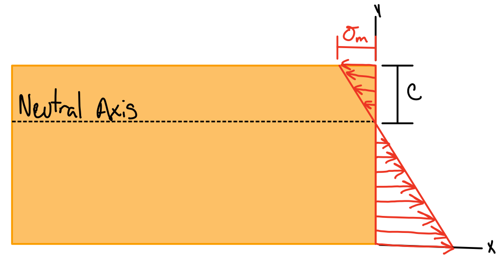
Absolute maximum stress.
Absolute maximum stress.
Elastic section modulus.
Heads up! - Extra
Composite beams builds on this content.
Recall that \( \epsilon_x = -\frac{y}{\rho} \) does not depend on the material properties of the beam, and is based only on the assumptions of geometry done so far.
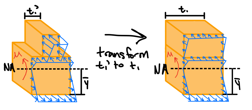
After obtaining the TRANSFORMED CROSS SECTION, we get
Note: the widening (\( n > 1 \)) or narrowing (\( n < 1 \)) must be done in a direction parallel to the neutral axis of the section, since we want y-distances to be the same in the original and transformed section, so that the distance y in the flexural formula is unaltered.
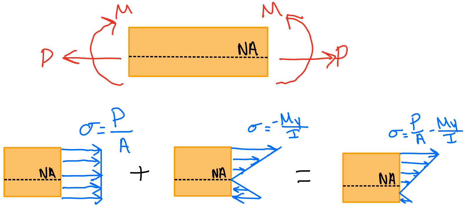
Eccentric Axial Loading in a Plane of Symmetry
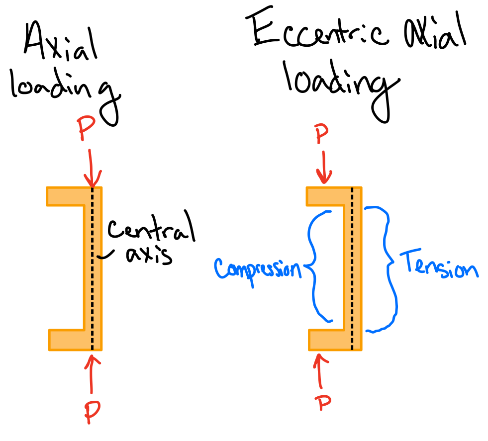
Equilibrium.