Solving complex systems
Composite Thermodynamic Systems
Before starting any problem, it is very helpful to familiarize yourself with the elements being addressed and any terminology being used. In approaching integrated, multi-device systems, following steps provide a framework that may avoid simple mistakes:
- Identify known states - states are known in a simple, compressible system when two intensive thermodynamic properties are known.
- Determine unknowns - stream states, energy flows, and mass flows are all potential unknowns.
- Write energy balances - the number of unknowns must equal the number of mass and energy balances to solve a system.
Step 1: Identify Known States
The state principle is a guide to aid in determining the number of independent properties required to fix the state of a system. When the state of a system is known, it can be plotted as a single point on a
Step 2: Determine Unknowns
We next apply our knowledge of thermodynamic devices to identify other energy flows in the system that might not be given. Although the primary purpose of this class is tracking the flow of energy, the preliminary step before writing any energy balance should be to identify mass flow streams and write any mass balances.
Step 3: Write Energy Balances
After determining the necessary mass rate balances, we can write energy balances. Depending on the amount of unknown, as variables needing to be determined there are two approaches to writing energy balances.
- Write an energy balance for each device where there is one system boundary around each device.
- Write an energy rate balance for the entire composite system that includes all devices within the entire composite system.
The total possible equations are determined by the sum of the number of `devices` that possess at least one unknown value (energy balances)
Example: Refrigeration and Heat Pump Cycles
Refrigeration and heat pump cycles differ from a power cycle in
For a refrigeration cycle, the required output is heat removed from the cold environment and the necessary input is the net work input
Refrigeration/heat pump cycle consists of the following types of thermal devices:
- Throttle: expansion valve
- Heat exchanger: evaporator and condenser
- Compressor
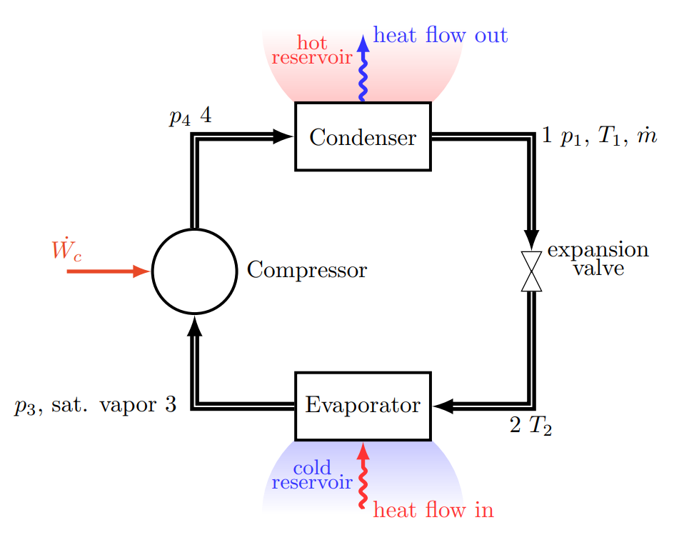
Step 1: The streams that have known states are streams 1 and 3. Known energy flow in the cycle is the power input into the compressor,
Step 2: The unknowns for this cycle are streams 2 and 4, and heat flow in (
Step 3a: The coefficient of performance of the refrigeration cycle,
The expression for the coefficient of performance,
Step 3b: For a heat pump cycle, the coefficient of performance,
The expression for the coefficient of performance
Transient Systems
A transient system is a system in which the time derivative related to the system gain or loss (such as mass or energy) is not zero, which is the opposite of a steady state system.
Transient Systems:
- Mass Flow
- Energy Flow
Transient vs. Steady State Example
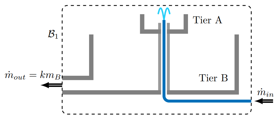
Imagine a two-tiered water fountain as depicted below. The maximum mass capacities of tier A and tier B are
Steady-State:
Drawing a system boundary,
from which it is clear that the fountain will operate at steady state whenever
Transient System:
If it rains, an additional mass flow rate
from which we conclude that steady state occurs when
Similarly, overflow might occur when the timescale
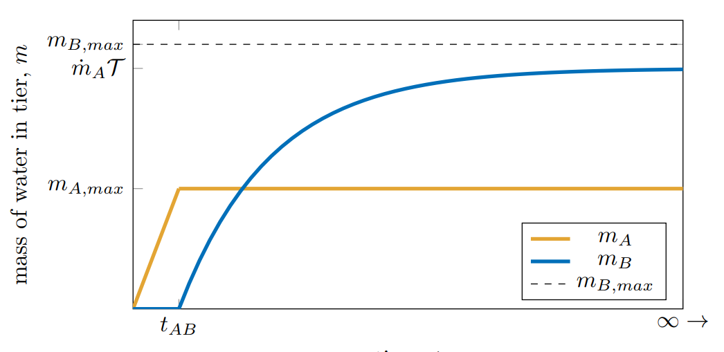
We model the transient process of turning on the fountain from an initially empty state (
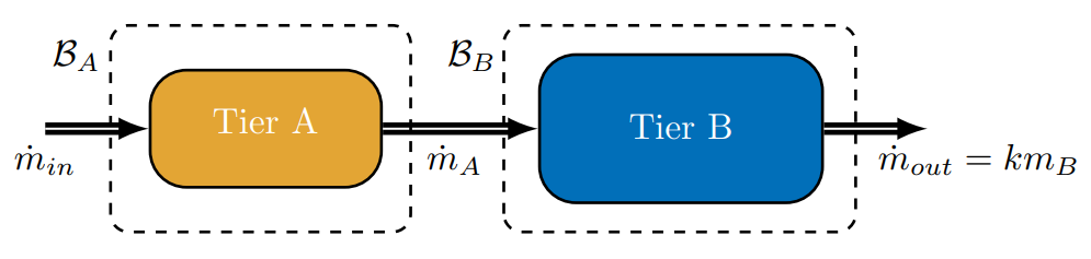
First, Tier A will fill. Drawing our system boundary around the Tier A block above (
Thus, the mass in Tier A increases linearly with time in proportion to the inlet flow rate. Tier A reaches it's capacity when
Drawing our system boundary around the Tier B block above (
It follows that the solution to this first-order, linear differential equation is
As