Trusses
Trusses composed of long, slender support members that are joined together at the ends with pins. The function of a truss is to transmit loads to a support joint. In this section, we will analyze a simplified version of planar trusses called simple trusses, which consist of two-force members connected by frictionless joints/pins.
Truss Assumptions
The main assumptions for trusses and truss structures are:- All loading is applied at the joints.
- The joints are frictionless.
- The weight of the truss is negligible.
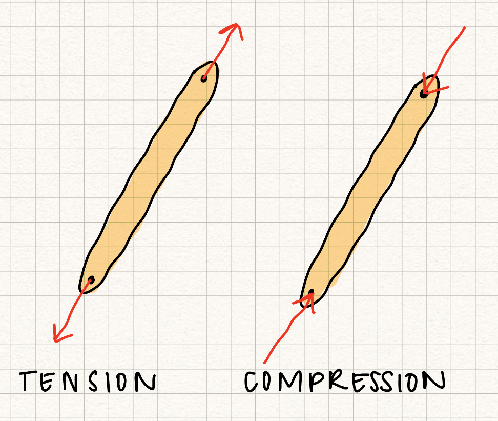
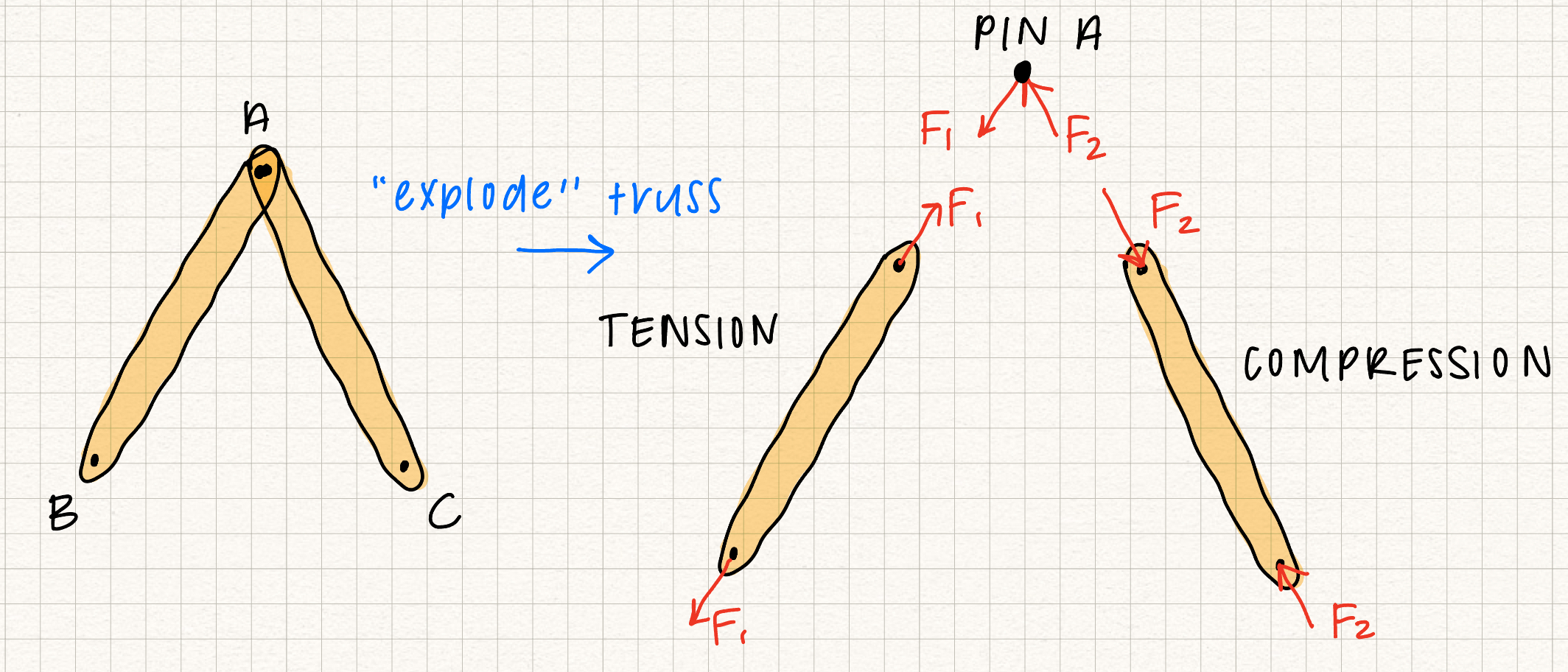
Because of these assumptions, all truss members are two force members, with the forces on the truss acting along the axis of the member. If the forces on the truss member "stretch" it, the member is in tension. If the forces on the truss member "squish" it, the member is in compression. In our class, we'll assume that members are always in tension. If we solve for the force in a member and get a negative number, we know that member is actually in compression.
Two Force Member
A two force member is a rigid body that has two forces (no moments) acting on it in two locations, say \(A\) and \(B\). Equilibrium of the two-force member implies
- \(|F_A| = |F_B|\)
- \( \vec{F_A} \) and \( \vec{F_B} \) act along the same line of action.
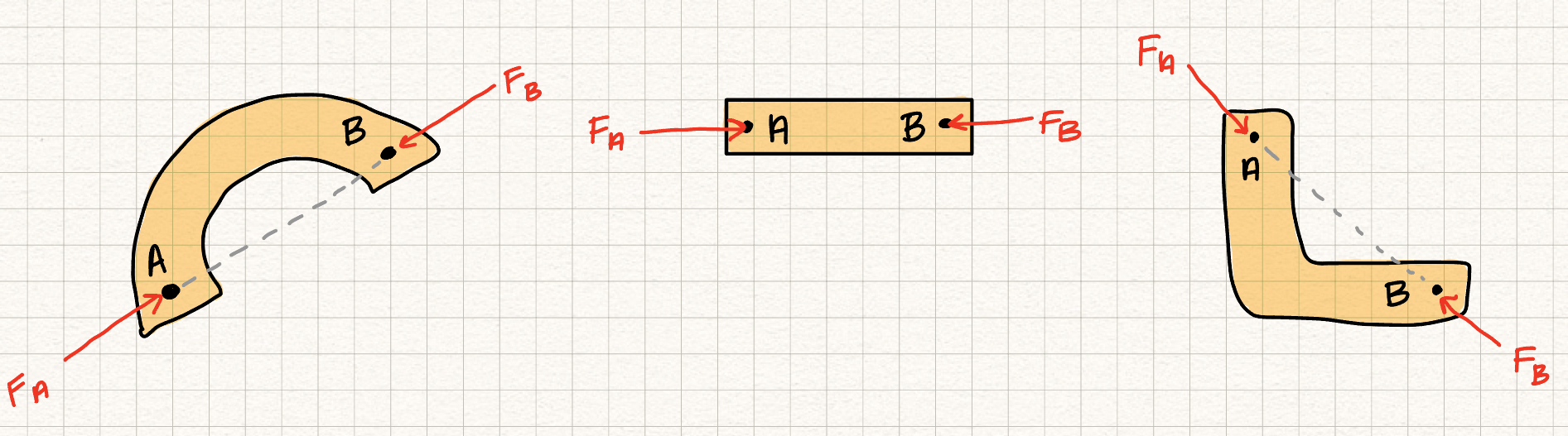
Specifically, the two forces act along the line between the two points where they are applied.
Zero Force Member
Zero force members are members in a truss structure that experience no force. They act as support trusses to add stability, but are not load bearing. There are 2 cases where zero force members occur:- Two noncolinear members share a pin with no support or external forces (Zero force member example, left - look at pin C!)
- Two colinear forces with a third noncolinear force on a pin (zero force member example, right - look at pins B and D!)
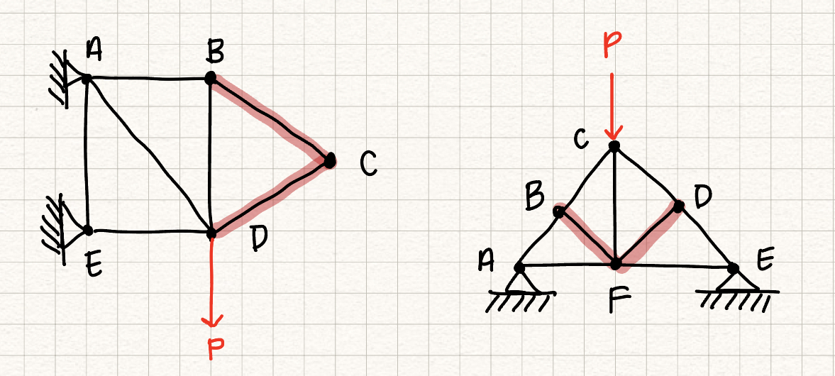
These rules will help us simplify trusses and solve for the internal forces in the desired members.
Drawing free-body diagrams on trusses is simple. As mentioned in the beginning, we will choose the entire truss as our system and draw the free-body diagram to determine the reaction forces on pinned/roller joints. Note we will need more equations and free-body diagrams on individual truss members to fully determine the reaction forces. The following is a diagram showcasing eliminating zero-force members.
Truss Analysis: Method of Joints
Method of joints for truss analysis:- Draw a free-body diagram for the entire truss and solve for the external reaction forces and moments at the supports
- Draw a free-body diagram of a joint with at least 1 known force and at most two unknown forces
- Use the equations of equilibrium for the joint to solve for the unknown forces
- Repeat steps 2 and 3 to find the forces in the trusses you are interested in.
Note: Remember that truss members that are in compression "push back" on the pin joints, and truss members that are in tension "pull" on the pin joints.
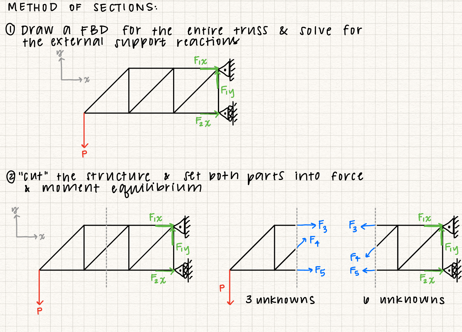
Truss Analysis: Method of Sections
The method of sections is helpful for determining the internal forces inside a truss member. The first step for the method of sections is the same as the firts step for the method of joints: Draw a FBD for the entire truss and solve for the external forces at the supports. Then, you "cut" the truss so that the internal force you want is "exposed" from the cut and analyze the two parts of the truss system to solve for the internal forces of the truss members.