Shear Moment Diagrams
Internal Forces
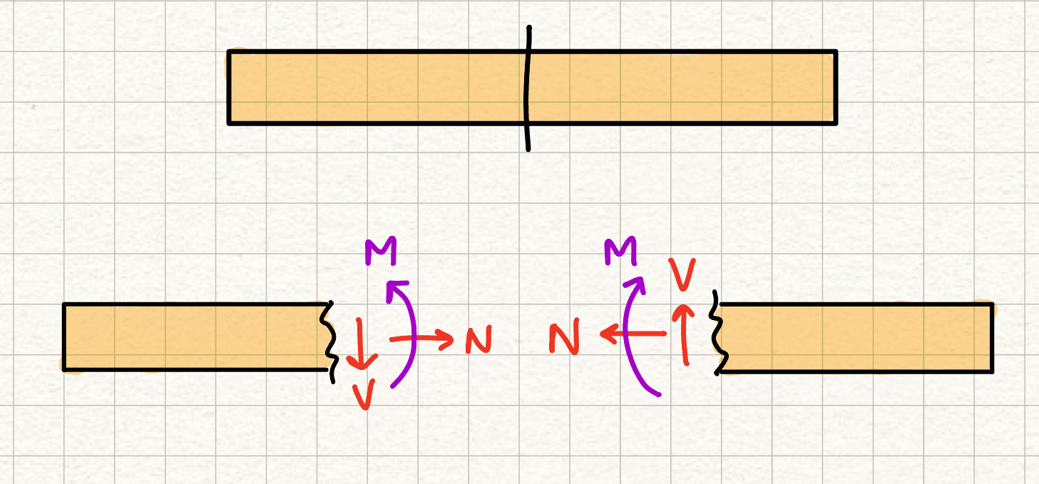
Internal forces of a member can be determined by creating an imaginary cut in a member, and then solving for the internal shear force, normal force, and bending moment (which, after the cut, become "external" forces that can be solved for).
To determine how the internal shear force and bending moment change throughout the member, shear force and bending moment diagrams are created. Shear force diagrams provide a graphical representation of the internal shear force within a member, and bending moment diagrams provide a graphical representation of the internal bending moment within a member.
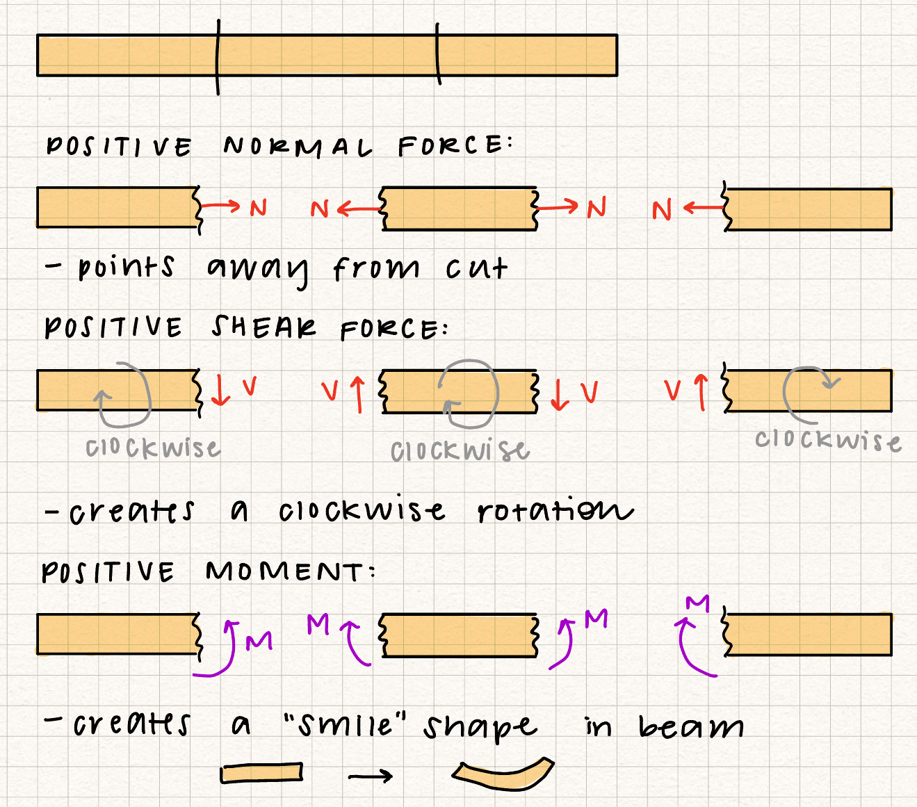
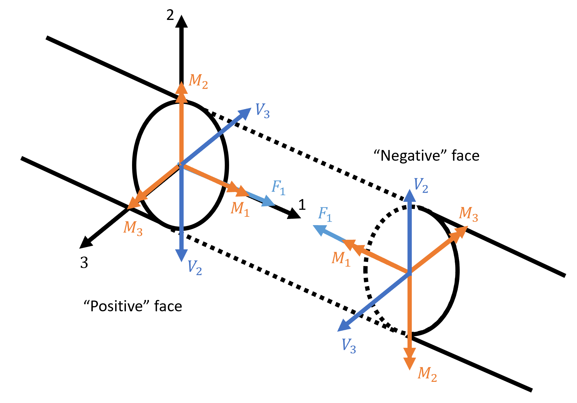
Sign Conventions
General Procedure
Creating a shear force and bending moment diagram allows us to create a graphical representation of \( V \) and \( M \) as a function of the position along the beam, \( x \). Therefore when creating internal loading diagrams we are trying to write equations for \( V(x) \) and \( M(x) \).
The general procedures for creating shear / bending moment diagrams are:
- Find support reactions
- Specify the x-coordinates
- Divide the beam into regions: one region for every change in loading
- Analyze each region by cutting inside each region and analyzing the free body diagram of the left side of the cut
- Apply equations of equilibrium to solve for \(V\) and \(M\) as functions of x
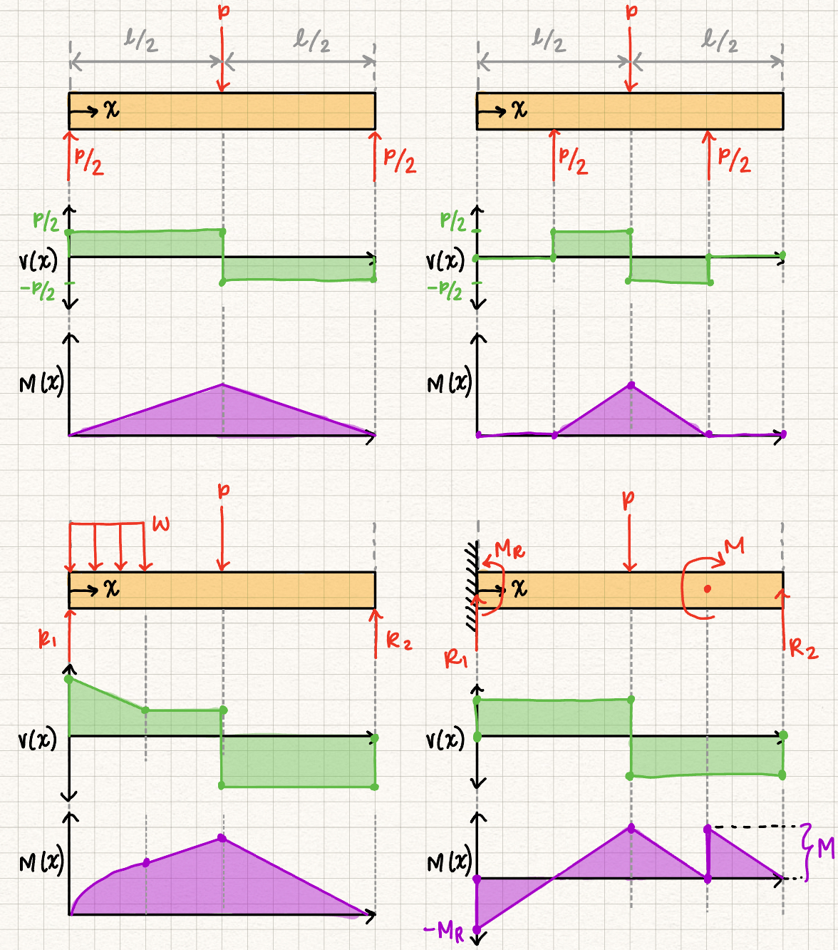

General Rules
- When there is an external concentrated force or moment, there will be a "jump" in the shear force or bending moment diagram
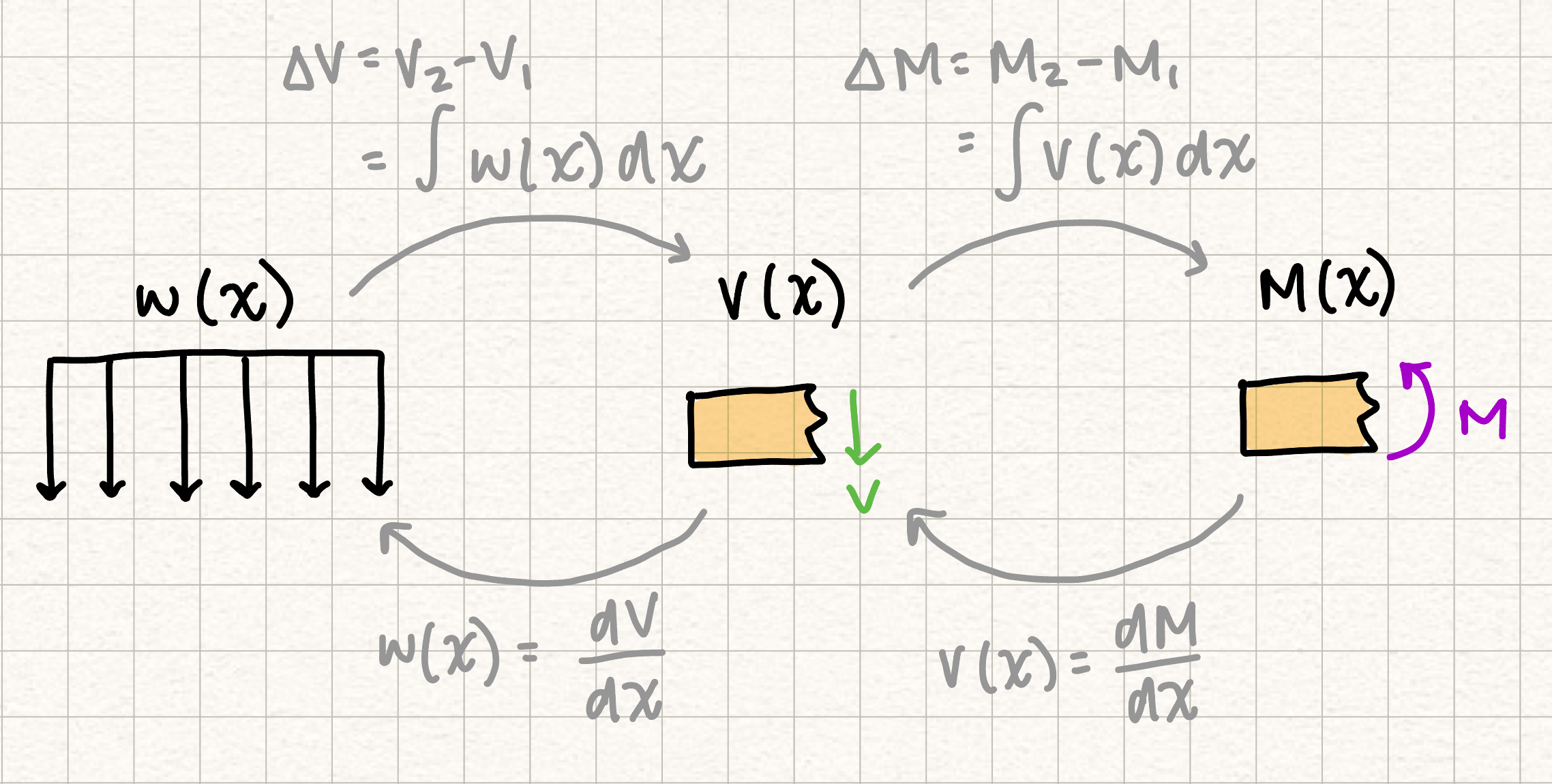
- \(w(x)\), \(V\), and \(M\) are related via the following relationship: