Transverse Shear
Stress Tensor from Pure Transverse Shear
For pure transverse shear loading conditions, the stress tensor can be simplified as shown below, depending on whether shearing occurs along the y or z axis.
Shear Stress in Beams
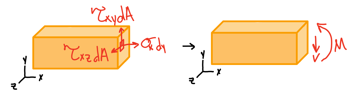
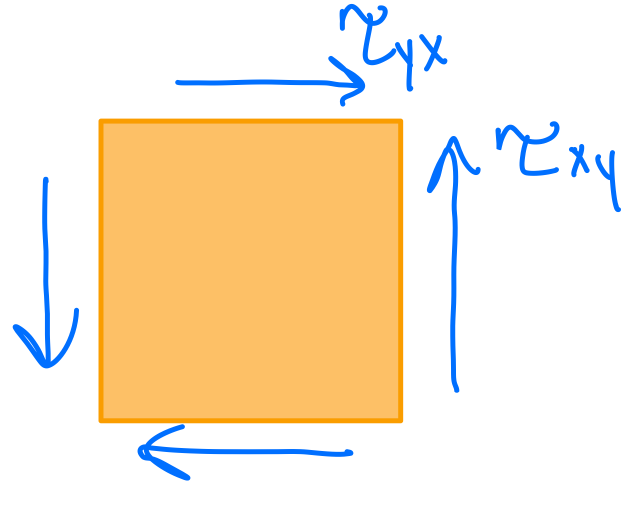
Symmetry of stress: transverse xy stress implies longitudinal yx stress.
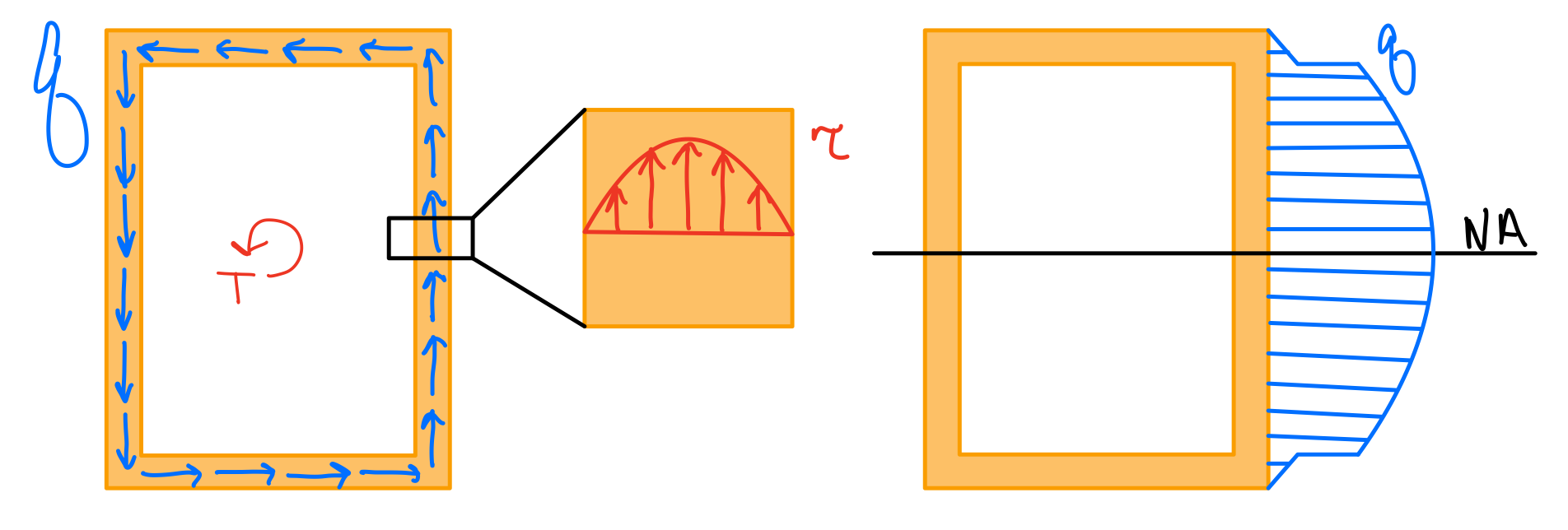
Average Shear Stress
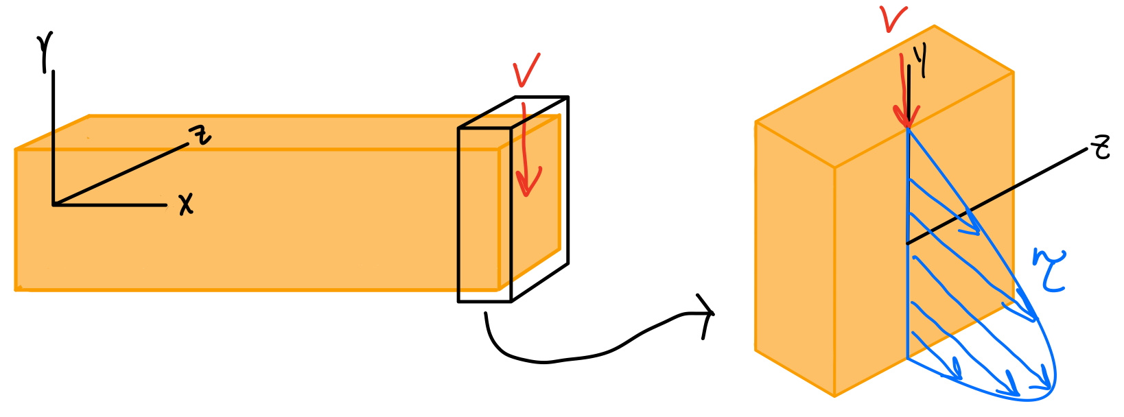

(B) An element distance \( y \) away from the neutral axis has a FBD of the bending moment stress distribution For this element to be in equilibrium, \( \tau_{xy} \) must be present.
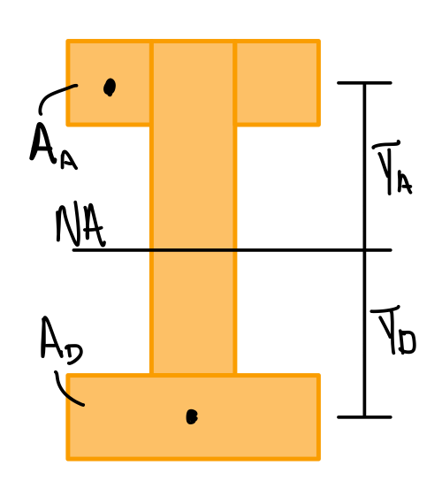
- \( V \) : Shear force
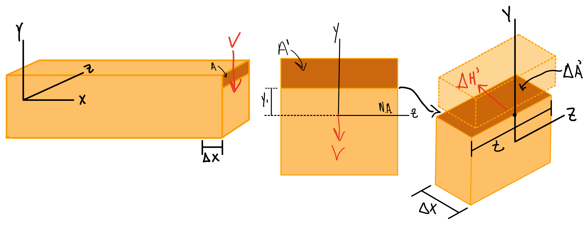
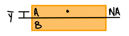
- \( Q \) : First area moment of inertia of cut section ( \( Q = \Sigma \bar{y}'A' \) )
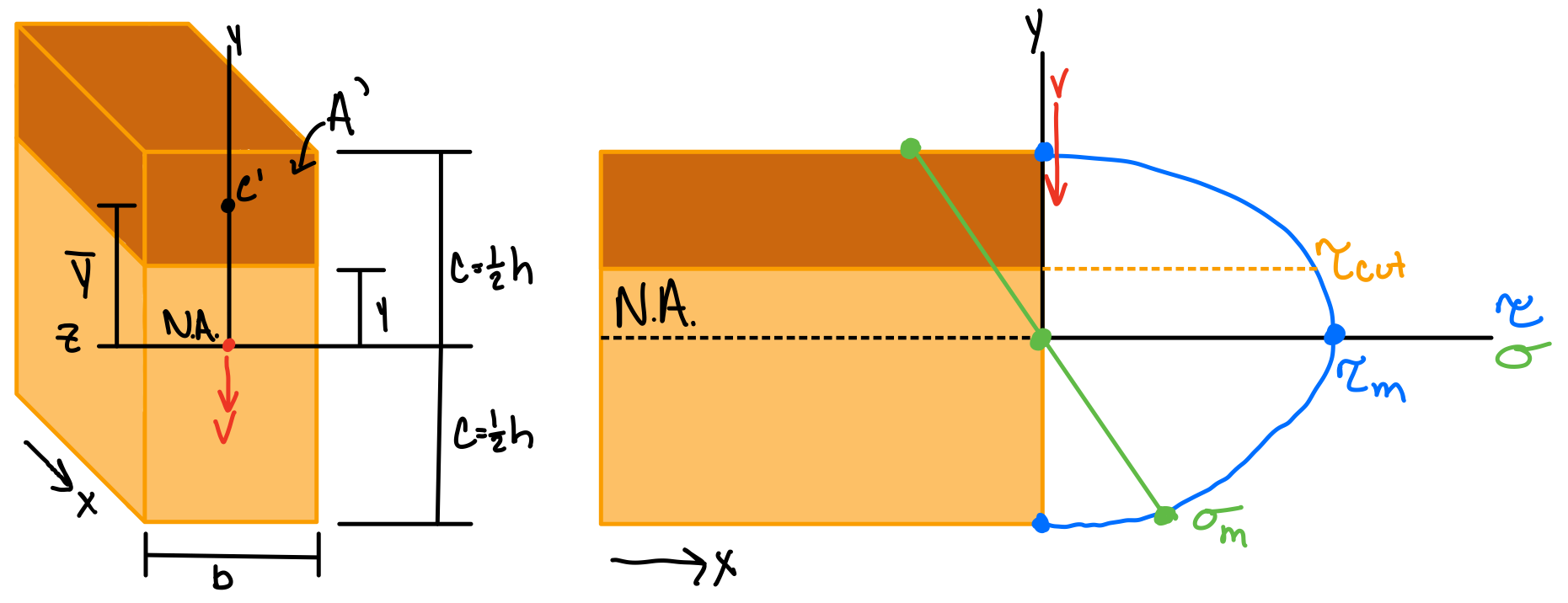
- \( I \) : Second area moment of inertia of whole cross-sectional area
- \( t \) : Width of cross section at given point
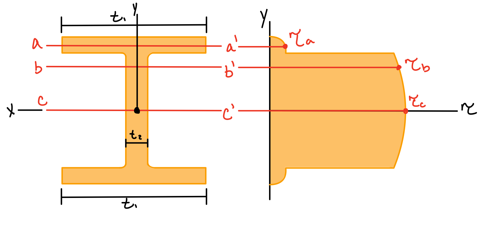
Rectangular Beam Cross-Section
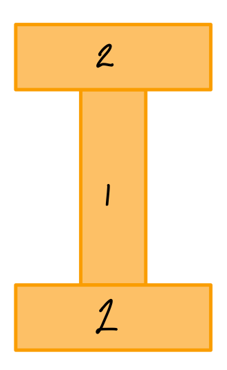
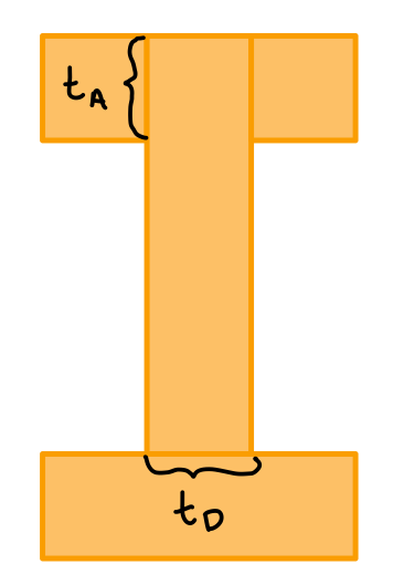
I-Shaped Beam Cross-Section
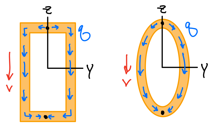
Built-up Members/Beams: Shear Flow
In some cases, it is more useful to look at shear flow (\( q \)) through a structure than internal shear stress.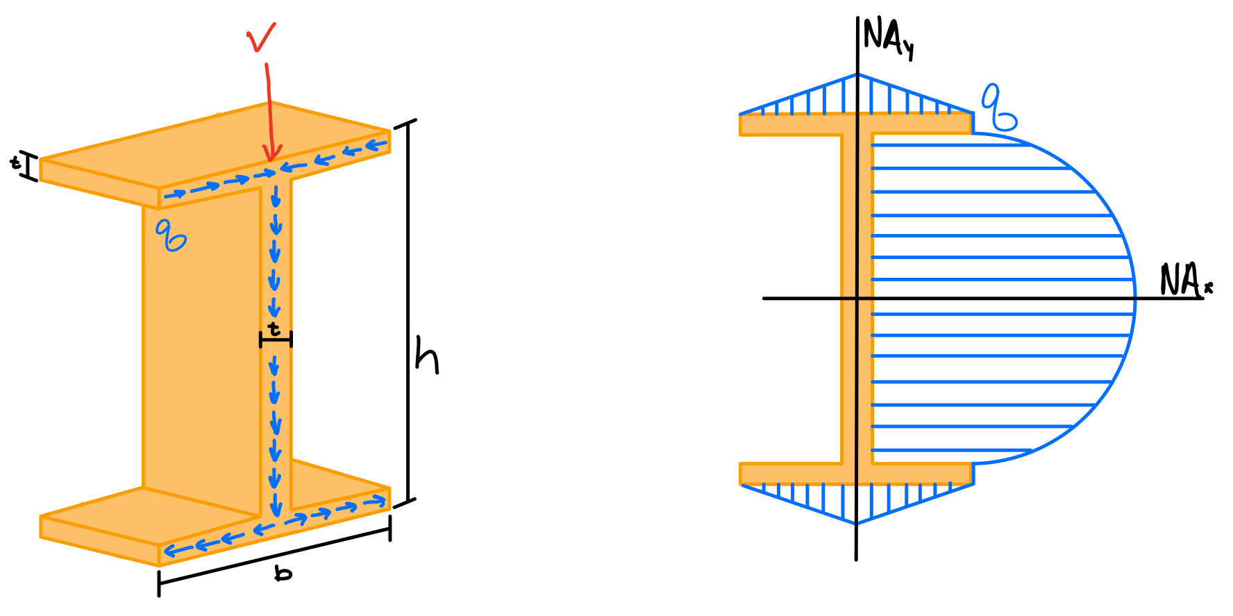
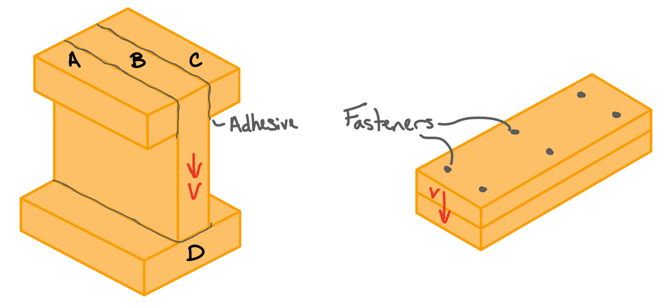
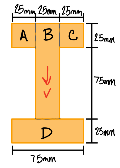
Adhesives supply resistance along the length of the contacting parts. Determine the minimum shear strength at these contacting/weak points using the shear stress equation.
The vertical shear is is \( V = 100 \text{ } N \).
Find the minumum required shear strength for the glue (\( \tau_{glue} \)).
Fasteners supply resistance at fixed intervals. Use the shear flow formula to analyze the beam.
The nails are at an interval of of \( \Delta s = 50 \text{ } mm \). The shear force is \( V = 100 \text{ } kN \). Find the shear flow (\( q \)) and the load at each fastener (\( f_n \)).

Since the nails are uniformally distributed, each nail is assumed to supply a shearing force \( f_n \) that resists the shear flow in the beam. Along a single row of nails (refer to the free-body diagram above), the total force is:
Because there are two rows of nails, the total resistance load supplied by the nails is:
To find the shearing force \( f_n \) in each nail, we equate the total force supplied by the nails with the total shear flow acting across their total spacing, \( q*s_{total} = 2q\Delta s \), to obtain:
Heads up!
shear stresses in thin-walled members builds on this content.