Strain
When forces are applied to a body, deformation, the change in length or shape, occurs. The change in length, divided by the original length, is the strain. We use strain to normalize deformations with respect to the size of the geometry.
Units
Dimensionless [mm/mm, in/in, or %]Normal Strain
Relative change in length of a line element oriented in arbitrary direction \( n \).
Average Normal (extensional) Strain
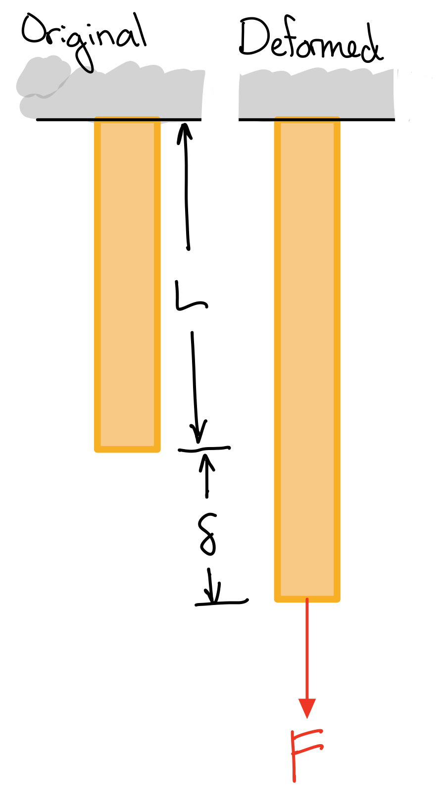
Length change divided by total length.
- Engineering or nominal (normal) strain: Average normal strain using the original (undeformed) total length.
Engineering strain. #sta-eng
- True (normal) strain: Integrate infinitesimal normal strains.
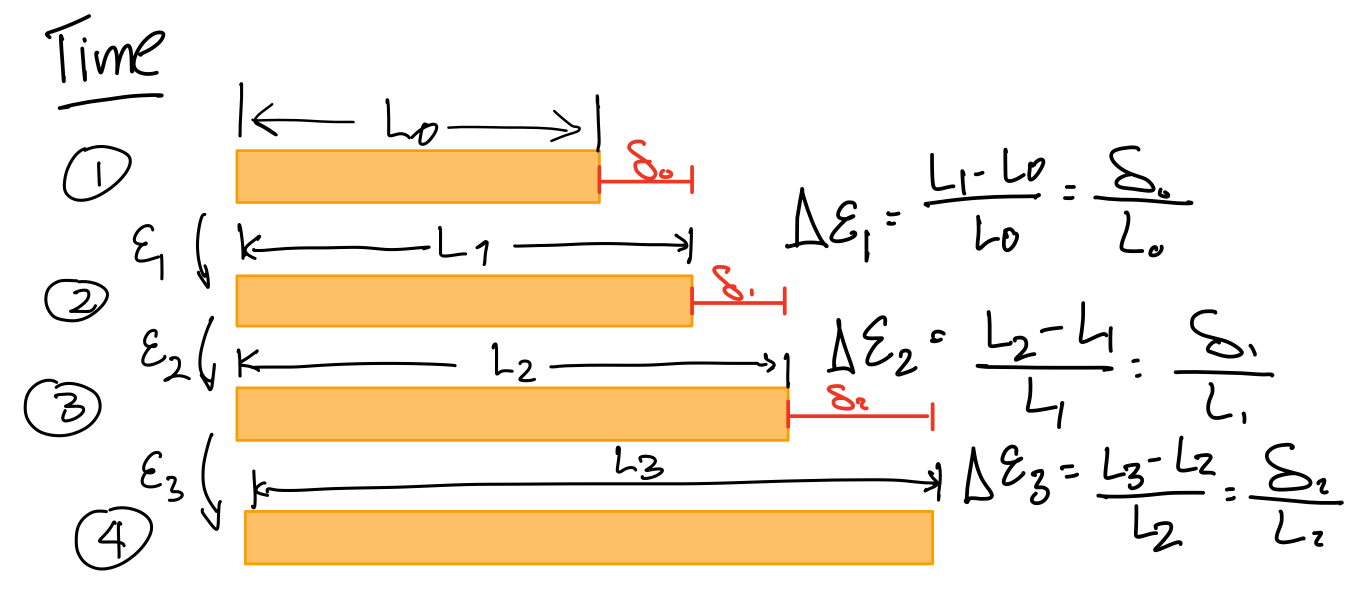 True strainTrue strain. #sta-ts
 - For small strain:
Small strain approximation. #sta-ssa
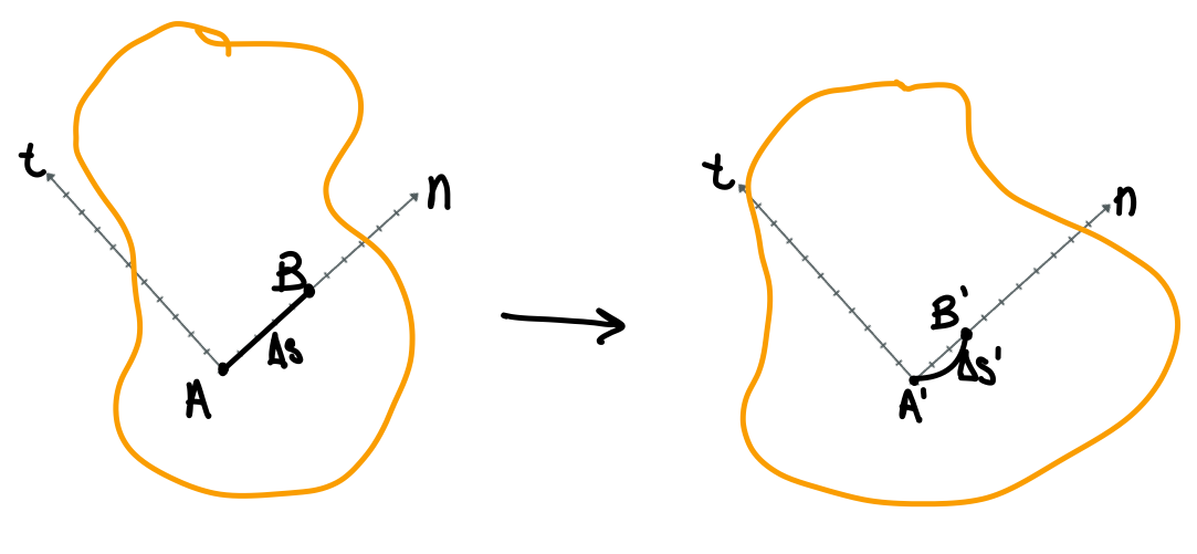
Shear Strain
Change in angle between line segments oriented in perpendicular directions \( n \) and \( t \):
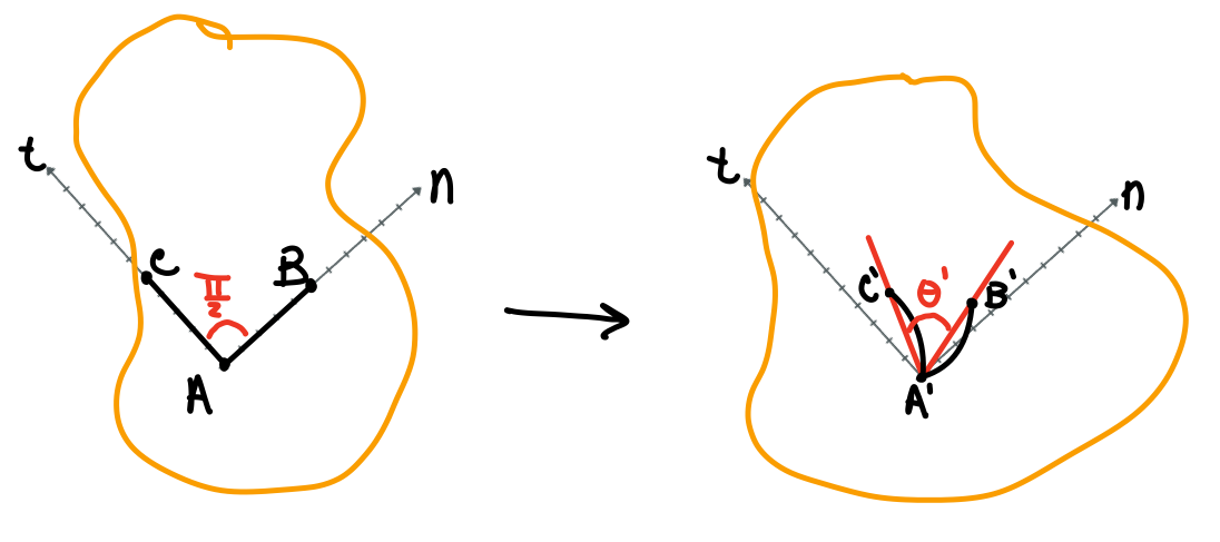
When strains are small, the small angle approximation, \( \sin(\theta)\approx \theta \), results in
Average Shear Strain
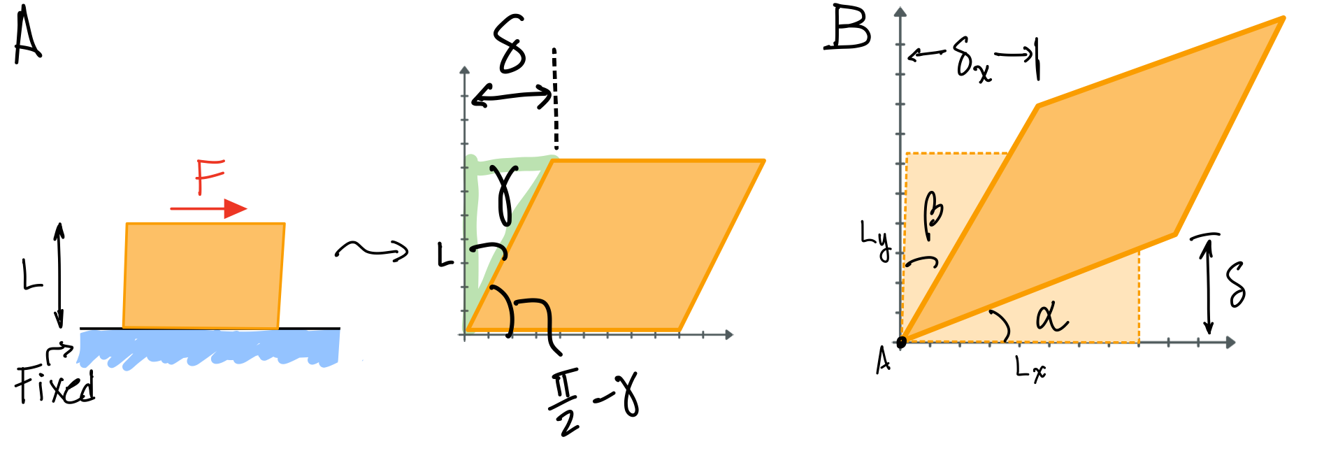
- Engineering (shear) strain: Compute angle from length changes and original (undeformed) total length.
- True (shear) strain: Integrate infinitesimal angle changes.
Strain Tensor
The components of normal and shear strain can be combined into the strain tensor. This is a symmetric matrix.
- Three normal strain components: \( \varepsilon_x, \varepsilon_y, \varepsilon_z \)
- Six shear strain components: \( \gamma_{xy} =\gamma_{yx}, \gamma_{xz}=\gamma_{zx}, \gamma_{yz}=\gamma_{zy} \)
The first subscript describes the surface orientation in the normal direction. The second subscript describes the direction of the stress.
Heads up!
Similar to stress tensor, strain tensor also builds on this content later in the course.
Learn more about this topic on the Stress Transformation page.
Direct Measurement
Initial and final lengths of some section of the specimen are measured, perhaps by some handheld device such as a ruler. Axial strain computed directly by following formula:
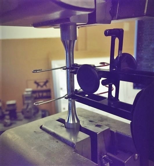
Contact Extensometer
A clip-on device that can measure very small deformations. Two clips attach to a specimen before testing. The clips are attached to a transducer body. The transducer outputs a voltage. Changes in voltage output are converted to strain.
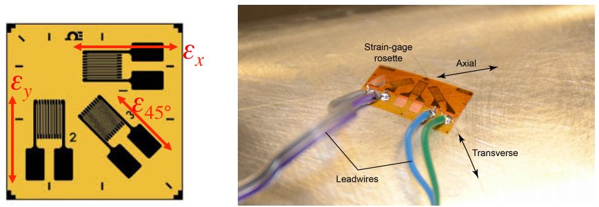
Electrical Resistance Strain Gauges
Small electrical resistors whose resistance charges with strain. Change in resistance can be converted to strain measurement. Often sold as "rosettes", which can measure normal strain in two or more directions. Can be bonded to test specimen.
Vibrating Wire Strain Gauge
A calibrated wire is set into vibration and its frequency is measured. Small changes in the length of the wire as a result of strain produce a measurable change in frequency, allowing for accurate strain measurements over relatively long gauge lengths.
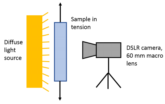
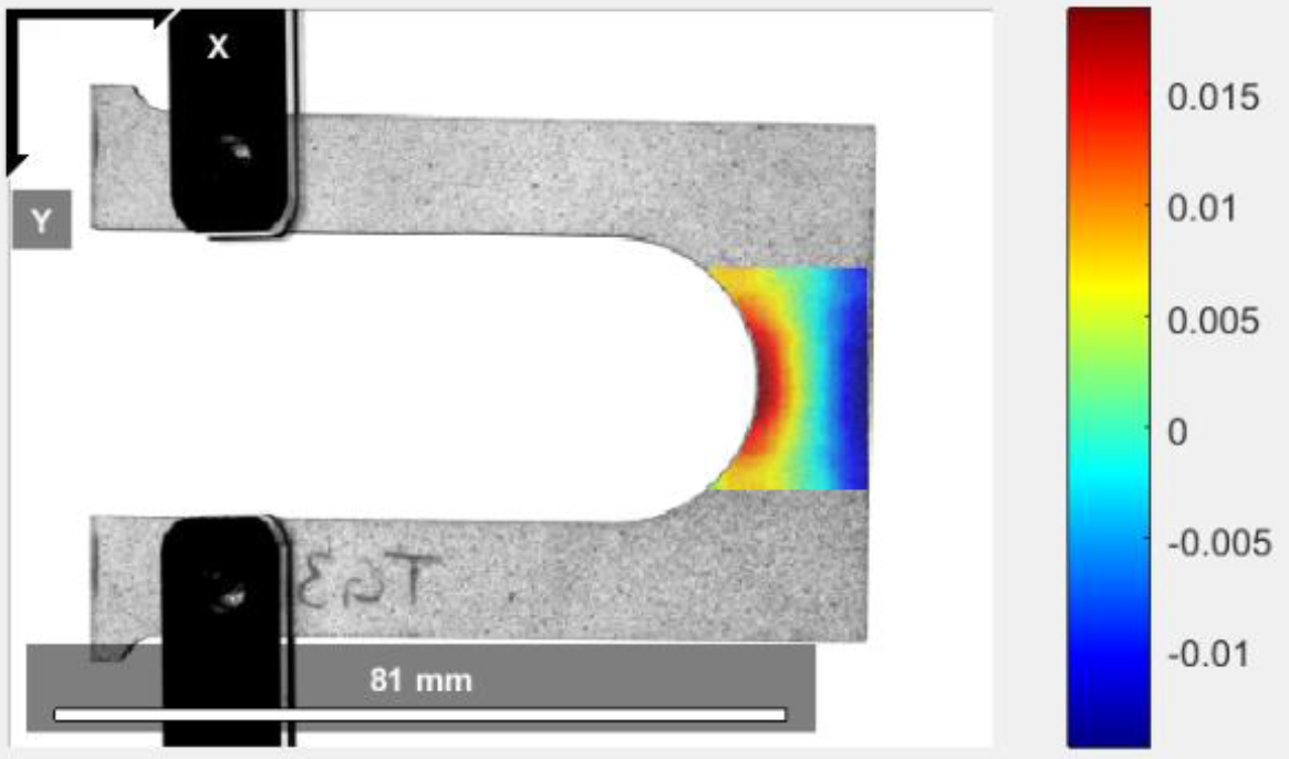
Digital Image Correlation (DIC)
Image placed on surface of test specimen. Image may consist of speckles or some regular pattern. Deformation of image tracked by digital camera. Image analysis used to determine multiple strain component.